Special Cutouts : Cabinet
In This Topic
Special Cutouts are essentially additional machining that can be added to various parts of the cabinet. They can be set up and saved into the and turned on with a check box when needed. Especially useful and quicker for one off things like cable entries.
At level, the Cabinet Machining > Special Cutouts page makes it possible to add one special cutout to each cabinet component. Special cutouts can also be exported to custom tables to save and re-use!
 Watch the 6 minute video
 first because when you first look at this screen it can feel a little bewildering. However, once familiar with it, it is not as bad as it looks. For a more detailed discussion,
watch the webinar.
We will first discuss the rules and then the options associated with each selection and examples of cutouts.
Special Cutout Rules
To locate information about any part of the following image,  click on the area of interest.
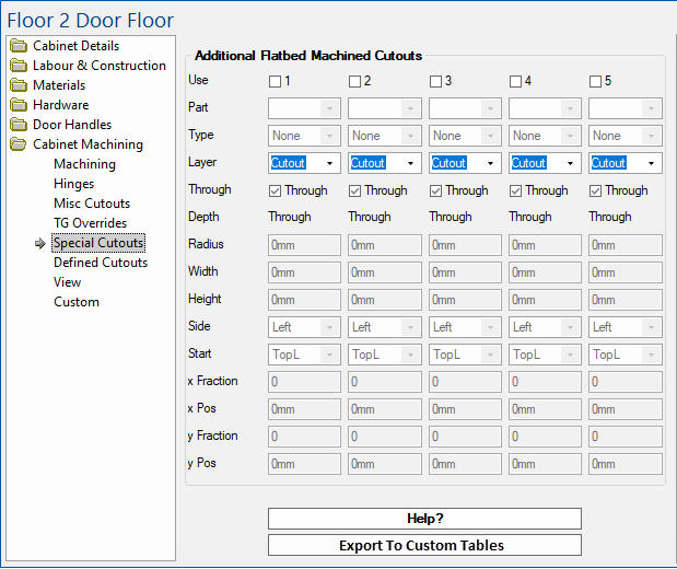
Use
Turn on to Use Additional Flatbed Machined Cutouts to apply required cutout.
Up to five separate cutouts can be applied to each cabinet.
If you need more than five, you can export and apply them as a
custom table. Type
These cutouts can either be Circles (half circles and quarter circles), Rectangles or Slots (open ended).

Click to Expand
It is recommended to use a rectangle instead of a slot, as it is easier to set up strategies in .
Circles and Rectangles
Specify the dimensions and the position of the centre.
- The centre of a Rectangle, Circle, or the end point of a Slot is specified either as exact co-ordinates or relative positions on the component, from a chosen starting corner.
Example of Position
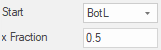
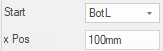
Here we want to centre a circles positioned 100mm across a component from its bottom left and half way up.
Do this by selecting BotL as the start position (green dot), x Fraction = 0 (left to right), x Pos = 100mm and y Fraction = 0.5 (half way up).
Note that circles need to be on the part entirely in order to machine - see Other Rules.

Click to Expand
Depending on their position, Circles are reduced to arcs if the circle would otherwise be part of the component. If the centre is within the radius of an edge, the centre automatically moves itself to be on the edge. Thus only full, half or quarter circles are actually cut.
A similar approach is taken for Rectangles, as for Circles, regarding their size (using the Width or Height instead of the Radius). For rectangles, the radius is applied to the corners.
Slots
Specify (1) the Width, (2) Side i.e. which edge it is cut from and (3) the x,y location of its end.
Example

Click to Expand
Slots are always cut with a semicircular end, beyond the selected end point.
Other Rules
The centre of a Rectangle, Circle, or the end point of a Slot is specified either as exact co-ordinates or relative positions on the component, from a chosen starting corner.
Holes for centres placed off the component will be positioned as if centred on the edge of the component.
If a specified width, height or radius exceeds the width or height of the component, it will be ignored.
These cutouts are undertaken without any regard to any other machining options (for example screw holes drilled to fix the component to another). The user is therefore responsible for the effect this may have.
Cutouts applied to Shelves will be applied to ALL shelves in the cabinet.
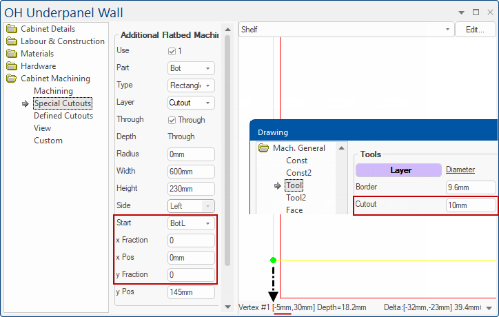
The cutout will not extend beyond the border of the part by more than half the diameter of the cutout diameter specified on the Mach.General > Tool page of your .
Example of Cutout diameter
Here the Cutout Diameter is 10mm and the cutout extends beyond the border by 10/2 i.e. 5mm.
Circles need to be on the part entirely in order to machine.
Example of Circle Cutout
The circle is entirely within the part and is displayed as a solid colour.
Options
Part
To which part (component) the cutout is to be applied.
Layer
What layer name to use for machining, this can be selected from the drop list, or typed manually.
If you type a layer name manually, ensure that there is a corresponding strategy in .
Through
Will set depth to Part thickness plus machine penetration value.
Depth
If Through is unchecked, then you can specify the depth of the layer.
Radius
Required by the Circle and rectangles corners.
Width
Required by the Rectangle and Slot.
Height
Required by the Rectangle only.
Side
Required by Slots only. Determines the side in which the slot is cut from.
Start
The start position from where to calculate the centre/end point.
The options are ‘TopL’, ‘TopR’, ‘BotL’ or ‘BotR’. These refer to the corners of the component as it is viewed from the chosen machining face defined on the Mach.General > Face page.
x Fraction
One way of specifying the position of the centre/slot end point.
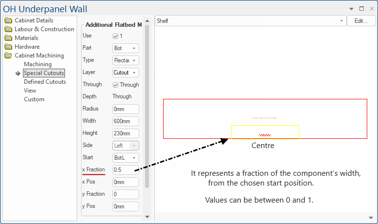
It represents a fraction of the component’s width, from the chosen start position. Values can be between 0 and 1 (up to 4 decimal places).
Example
Here the resulting position would be halfway across the component (regardless of the components size.)
Regardless of the start position, the ‘x Fraction’ always positions away from the chosen start point, there is no need to try and use negative numbers. (e.g. 0.5 from TopR would result in the same position as from TopL).
x Pos
The alternative method of specifying the position of the centre/slot end point. It represents an actual distance from the chosen start position.
Example of x Pos
Here the resulting position would be 100mm from the bottom left hand corner.
Regardless of the start position, the ‘xPos’ always positions away from the chosen start point, there is no need to try and use negative numbers. (e.g. 100mm from Top Right would result in a position 100mm towards the Top Left).
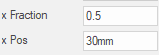
x Pos can be combined with x Fraction
To centre circle 30mm from the centre use ‘0.5’ as x Fraction and ‘30mm’ as xPos, from the appropriate starting corner.
y Fraction
Similar to x Fraction but dealing with the position of the centre/slot end point in relation to the component’s height.
y Pos
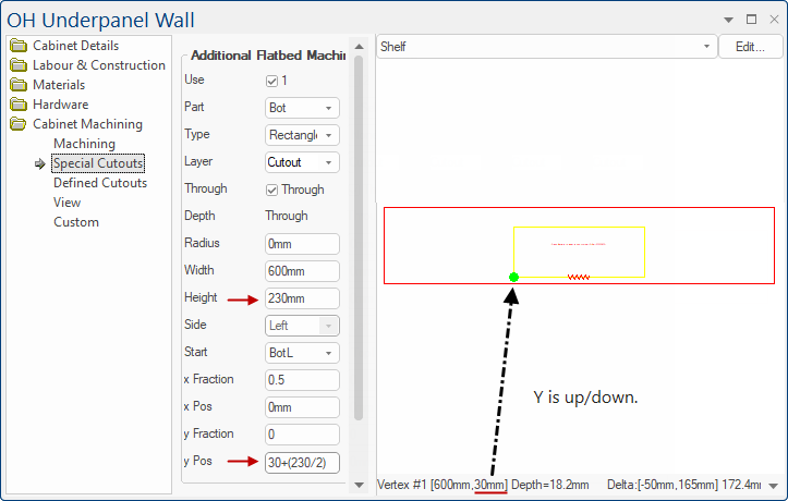
Similar to xPos but dealing with the position of the centre/slot end point in relation to the component’s height i.e. up/down.
y Pos = distance from front + (cutout height / 2) e.g. 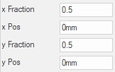 formulas can be entered in edit boxes (See Step 3 of Tutorial)
Examples of Special Cutouts
To view cutouts for Machining in the Preview Pane either ...
- select options on the Cabinet Machining > View page i.e. turn on the View checkbox and select part to view from the drop list.
or
- using the Preview Pane, available from all pages i.e. from the Preview Pane menu select Machining and then use the drop list.

Cabinet Machining > View page - Click to see both the View page and Preview Pane options
Tutorial
When measuring a drill centre, you need to measure from the centre of the hole/cutout (not the edge).
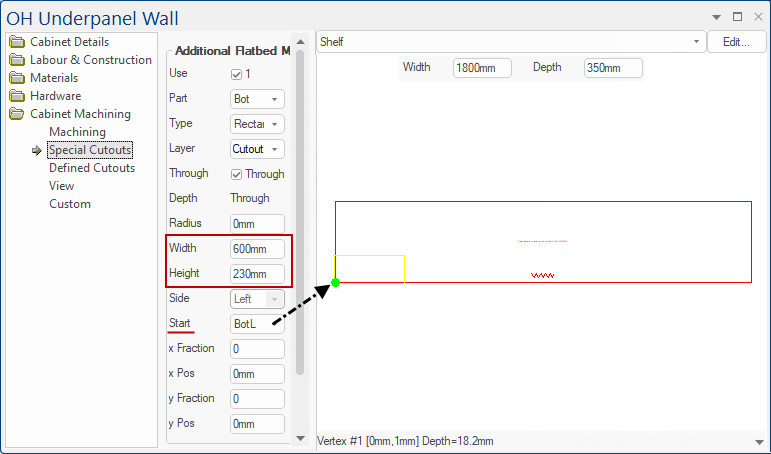
To explain how to position we will use an Overhead Underpanel with a Width of 1800mm and a Depth of 350mm.
Step 1: We will create a rectangle cutout with a width of 600mm and a height of 230mm and measure from the Bottom Left (BotL)
Example
Step 2: Now we are going to centre it (left to right) i.e. set x Fraction to 0.5
Example
Step 3: Now we want to have a 30mm clearance from the front edge of the part to the front edge of our cutout.
y Pos = distance from front + (cutout height / 2) i.e. 30+(230 / 2) = 145
Example
More Examples
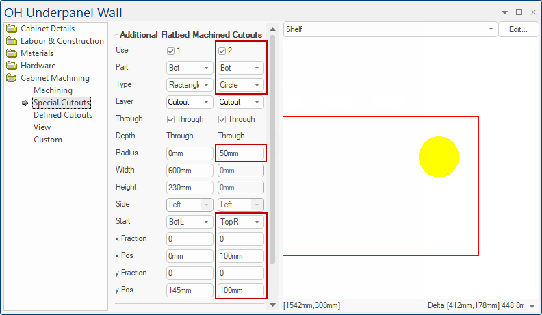
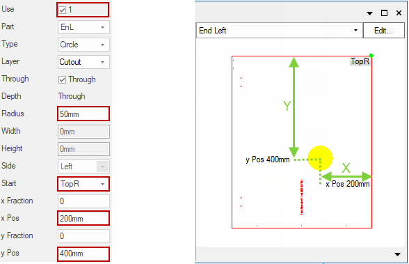
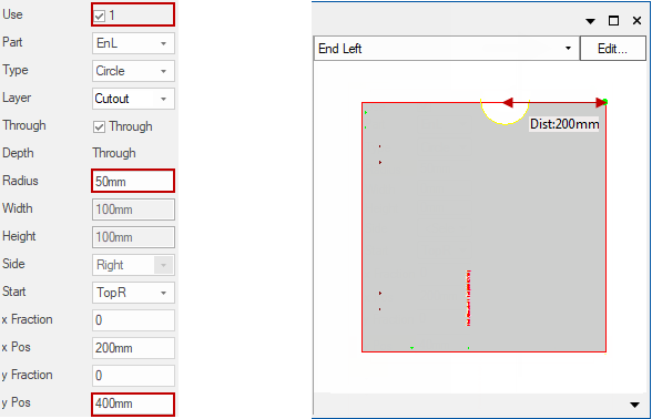
Circle
Use options Radius, Start, x Pos, y Pos:
This would cut a circle of radius 50mm in the Left End.
The centre of the circle being 200mm to the left of and 400mm down from the top right corner of the component.
Semi Circle
Use options Radius, y Pos:
Similar to the example above, but this would cut a semicircle of radius 50mm in the Left End.
The centre being 200mm to the left of the top right corner and on the edge of the component.
This is because the yPos is less than the radius, so the circle would have been cut off. As mentioned in the ‘Rules’ above, when this happens the centre is placed on the edge of the component.
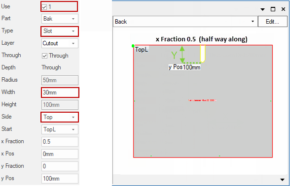
Slot
Use options Type, Width, Side:
Cuts a slot in the Back component, of width 30mm, down from the Top of the component to a position 100mm below the top and halfway along.
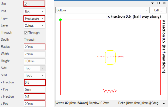
Rectangle 1
Use options Type, Radius, x / y Fractions, yPos
Cuts out a rectangle into the Bottom part component, 75mm wide and 100m high, centred 20mm above the middle of the component. The corners being cut with 20mm radius.
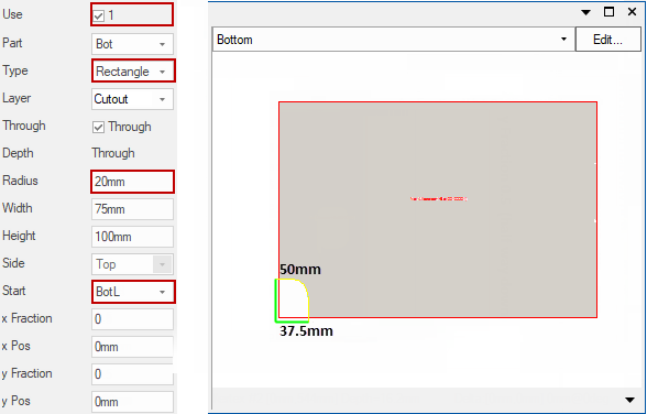
Rectangle 2
Use options Type, Radius, Start
As the centre of the rectangle is the bottom left hand corner, this results in a cutout from the part of only 37.5mm wide and 50mm high. The corners being cut with 20mm radius.
This allows you to export your special cutouts to custom tables to save and re-use! This makes it quicker and easier to get special cutouts that you use commonly. And the best part: you don't need to know how to use custom tables. CabMaster will do it all for you.
When you are working on a special cutout in the cabinet properties page all you need to do is put your desired cutout details in, make sure the Use tick box at the top is ticked, and then click the Export To Custom Tables button.
The Export to Custom Tables button, when pressed, opens a Wizard which allows the user to select the cutouts they which to export.

Click to Expand
Cutouts without a Type or of the "Slot" type cannot currently be exported.
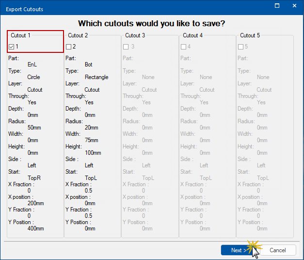
Step 1: Which cutouts would you like to save?
Enable by ticking the Use checkbox of the cutout that you want to save.
Click the Next
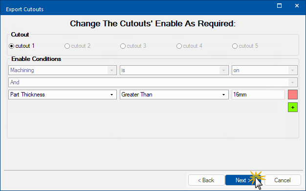
Step 2: Change the Cutouts Enable
Cutout radio button
Allows the user to select the cutout to edit.
- In this example, as we only selected 1 cutout in the previous step, only Cutout 1 radio button available.
Enable Conditions
You can enable conditions for when the cutout is used - machining is on by default. (You don't need to add any further conditions to save your special cutout, but the option is available if you want to use it.) With no alteration, the cutouts enable will be "yes".
Users edit the enabled condition by adding terms, as discussed below. When complete, press Next.
Add Condition
To add a new Condition, press the  (green plus button)
Condition
To build a Condition select the drop list left to right do the following:
- the Property to check -
- in this example, Part Thickness
- the Comparator
- in this example, Greater Than
- the Value to compare to (depending on the Property can be a drop list or edit box)
- in this example, 16mm was typed into edit box.
AND / OR
Additional selection boxes allows the user to chain conditions with AND or OR.
Remove
To remove a Condition, press the  (red minus button). A confirm 'remove' message will be presented, click Yes if you wish to continue.
Step 3: Choose FileName for Export
Type in your required filename.
- In this example the File name typed in is 'Sample My Cutout' (click on image)
- This file will be exported with this name to the <your CabMaster folder>\Table\Machining\Custom\ folder.

Type in your File name - Click to view example
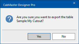
Press Next and you will be asked to confirm 'export'.
Click Yes if you wish to continue and export the table. This will save your special cutout for later use.
Be careful not to overwrite existing tables unless you are completely sure that this is what you want to do.
Export Complete
Now you can either open the table that has the cutout saved in it, or you can click Finish to complete the process of saving your special cutout.
If export is successful, open the export using the Open Table button.

Open Table to view. Click Finish when completed.
Open Table
This file will be located in <your CabMaster folder>\Table\Machining\Custom\ folder.
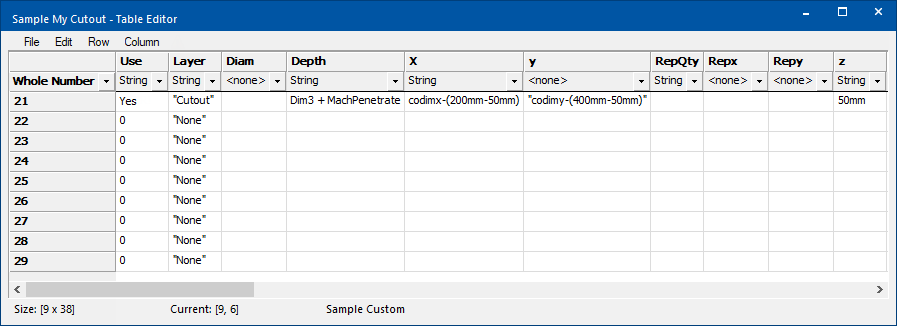
Table Example
Example of file created for Circle Cutout where Rows 21-30 are used.
Applying Custom Cutout
You can now use this Custom Table and apply settings to other cabinets parts in any cabinet on your drawing/job by going to the Cabinet Machining > Custom page.
Video
This video discusses special cutouts in CabMaster. (5:55mins)
Webinar
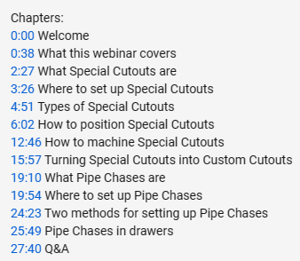
In this webinar, 'Using Special Cutouts and Pipe Chases in CabMaster', we will show you how to create a special cutout, how to customise your pipe chase and more. [28:58 mins]
See Also
Cabinet Labour & Construction
Cabinet Design & Construction